Investigation of wiring problems and limp mode

Lextasy

Banned
Messages
19
Dear community,

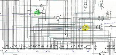
I think I need your help as I have been investigation my limp mode problems and have run into wiring issues which I cannot trace back to my original drawings, but hey maybe these are official modifications!.
The car has been running outstanding for a long time until I decide to change the Bosch accelerometer potentio meter.
First and for all I could not rid of the limp mode; leaving me to believe the problem lies somewhere else, secondly I found wiring which is hard to understand what is going on here.

I have written it down in a word file since it does have a lot of schematics in it.

Please visit this link, since I cannot add it as attachment: https://1drv.ms/w/s!AlL611R-4KdPg95-wWWUs_bxSFNUVg


Enjoy!
 

andy15

Junior Member
Messages
42
Interesting reading. Can't come with any assistance yet, but it looks similar to the modification I have in mine.
As I remember I have 3 wires cut and 3 new cables to the ECU. Could you confirm which of the six cables in the plug were cut?
Another question - the new potentiometer - is it brand new or used one?
 

Swedish Paul

Member
Messages
1,810
Don't know what if you're talking sbout the same thing, but as I'm an arm chair enthusiast, didn't they change that an a wheeler dealer 3200 episode and had to plug it into some diagnostic tool to tell the ecu to relearn the on/off positions. Can imagine limp home mode being enforced if it didn't know where the accelerometer was.
 

andy15

Junior Member
Messages
42
I watched Wheeler Dealer again and Ed did connect SD2, to check voltage after performing throttle reset procedure. Lextasy's voltage looks OK.
BTW, was the voltage measured at the ECU or at the pod? I would compare the values at both locations to eliminate wires and pod issues.
 

Contigo

Sponsor
Messages
18,376
You need to recalibrate the new pedal pot. Turn ignition to MAR for at least 2 minutes and then ignition off. Then turn to MAR and press the throttle all the way to the floor for at least 10 seconds then turn off. Start the car as normal and it should be Out of limp mode (no CEL). If that doesn't fix get us the fault codes.
 

Contigo

Sponsor
Messages
18,376
Just seen the document Lextasy and OMG someone has really bodged those wires! :(

Like trying to find a needle in a Haystack now.

Voltages are all correct. There was a wiring mod where two grey wires were cut and left taped up. God knows how you are going to fix this one.
 

Lextasy

Banned
Messages
19
Hi guys,

Thanks for the input, I am not very worried to fix it, I just have to find a good scan tool to help me read the codes ( have been in contact with Sander) and Mr. Shanks who makes the contactless style, which I want to fit secondly. But I have to also get intouch with some Maserati dealers who can tell me more about possible wiring mods,. I have heard about rerouting the ground since per Original design it was quiet long.

I have one certainty: it ran very well in the past so the wiring design can't be that wrong, but the way it was conducted was ridiculous. Mind you this car has Always been serviced by Maserati in Dubai and I have all the bills with the car but can't find much.

As test I can rewire as Original and see what it brings, I just am not certain of connection C36 which is wired but per Original design not connected and I have no idea what this is.

It is fun but also depressing as I like to drive the car..but I know what patience is, as it took me 2 years to complete my Ghibli!

rds
Jeroen
 

Lextasy

Banned
Messages
19
& Andy: you are right I should check at the ECU too; we checked at the pod only, it was quiet hard to get at the ECU pin config, but the way could be to remove the connector housing and plug in carefully.
 

davy83

Member
Messages
2,823
Hi lexstasy. I have your document and i will try to outline the rework that has been applied at the factory to my car, but i am not at the car jsut now and also don't have my workshop manual, can you share the page from the manual which shows the pin locations and functions of the multi-pin connector on the ECU? i think i can describe the rework to you from that.
 

davy83

Member
Messages
2,823
Ok i think what i would be trying to do (and what i think the factory rework is) the two signal wires (yellow and white on the sensor connector) marked in yellow on the drawing here, you want to wire these directly to the ECU connector block B. you are not altering the wiring just making it shorter and removing the wires from the wiring looms where they pick up noise. The factory rework is four wires, so the two signal wires and i am pretty sure its also the 0v wires shown in green on the diagram here. These in the original scheme go to a wiring block on the body (as the diagram shows) and these are re-wired again directly from the sensor to the ECU connector block, using as short wires as possible. Now according to the diagram here the 0v connects to a pin on block C on the ECU, and in the absence of any better ideas i would run the two 0v wires to this pin. Now i have a feeling there is a 0V pin on block B where the signal wires are connected to, and this is the one to use. But without the pin descriptions for that connector block i cant say for sure that there is a 0v pin on that block B connector. Some one with a 2001-2002 car could perhaps oblige with a photo of the ECU showing the four rework wires? pull the carpet down to the right of the pedal area and the ECU is just sitting on the right. Hope this rambling helps, and i think the 0v wires are the biggest problem, so do them first see if it helps!

rework wires.jpg
 

Attachments

  • wiring mods.jpg
    wiring mods.jpg
    20.8 KB · Views: 70

Lextasy

Banned
Messages
19
Hi Davy,

Thank you for the input, much appreciated I will sit down and read it carefully, it seems to make sense.
With regards to your question about the ECU and pin location, I belive in my document I have put picture of the A, B C and D section with leganda of what the pins mean. Is that what you are referring to?

rds
Jeroen
 

Lextasy

Banned
Messages
19
@Davy,

This is the configuration:


Pin 1 (Red Green) to ECU B2 : Accelerometer pedal sensor 2 signal ( the signal between 0.3 and 3,2V
Pin 4 (Red Yellow) to ECU B8: Accelerometer pedal sensor 1 signal ( same)
Pin 2 (Red Black) from ECU C34: Accelerometer positive supply 5 V (S48)
Pin 5 (Red Black) from ECU C34: Accelerometer positive supply 5 V (S48)
Pin 3 (Grey) to ECU C8; negative supply (ground) for Accelerometer and pressure sensor (0V)
Pin 8 (Grey) to ECU C8: negative supply (ground) for Accelerometer and pressure sensor (0V)
 

Lextasy

Banned
Messages
19
some updates..

A little heads up.

- I have installed the new pedal potentiometer ( the contactless type) and from the measurements it seems a good fit!
So far the good news.. the Bad news is that we keep getting limp mode, even so we rewired the ECU as per drawings.

Second good news; since I need to get the error codes; we finally succeeded to connect the software of Sander and what a surprise to see fault codes visible.

MAy I ask the community to have a look at the codes and advise me?

Many thanks.

20170309_111512816_iOS.jpg