Ghibli suspension overhaul

spacecadet

Member
Messages
378
Use a mini-ductor to solve this? (have become quite affordable)

Tried a heat gun, it's not rust, but some tension between the parts?

They are not threaded just stuck, I used an impact driver on mine so didn't damage the head that much.

It is worth trying;

Remove the three bolts that connect the hub to the top mount, leaving only the bottom part connected and using a mallet and piece of wood see if you can hammer the top part of the hub outwards and downwards to try and break the seal on the bottom bolt ? Obviously hit the wood not the hub !
The twisting action may help to break the seal.

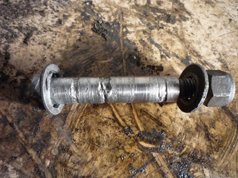
Good idea, unfortunately didn't really help. Knowing these are not threaded allowed me approaching them in a more spirited way. After 3 hours removed one and a half. The one which came out quite easy only with a socket is in a pretty bad condition, even damaged the hole in the arm too. Will post a photo soon.
 

spacecadet

Member
Messages
378
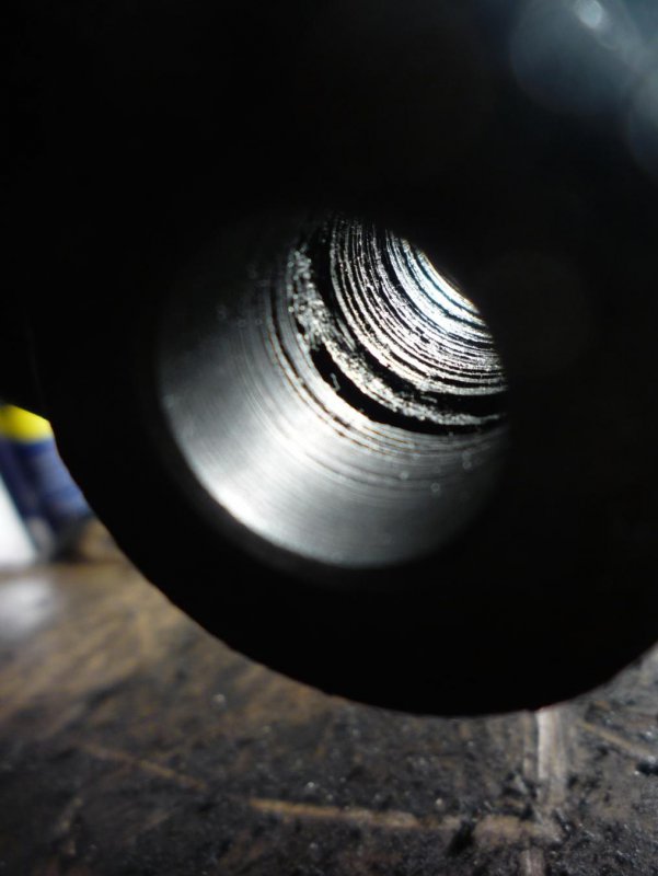
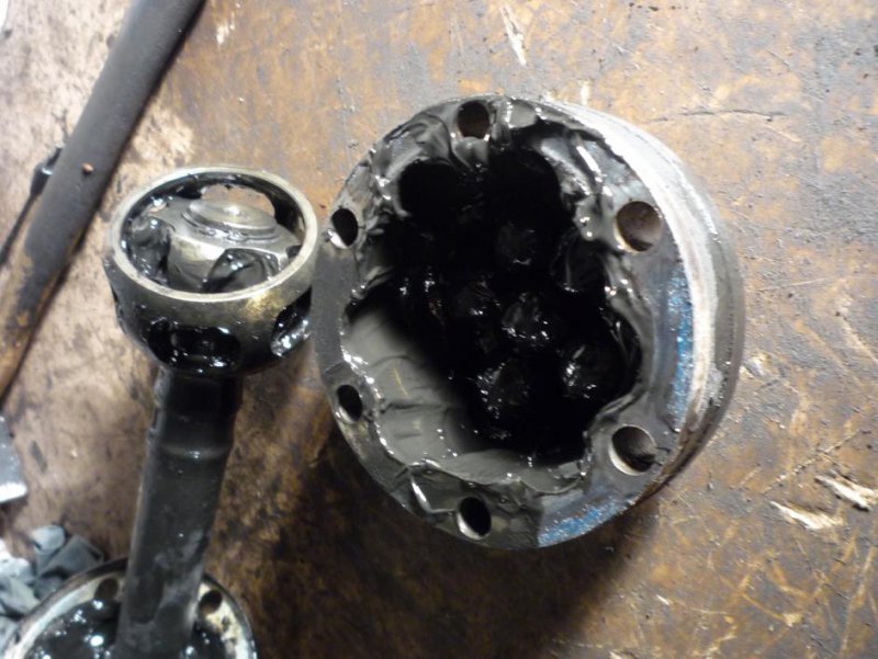
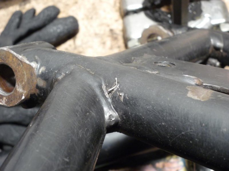
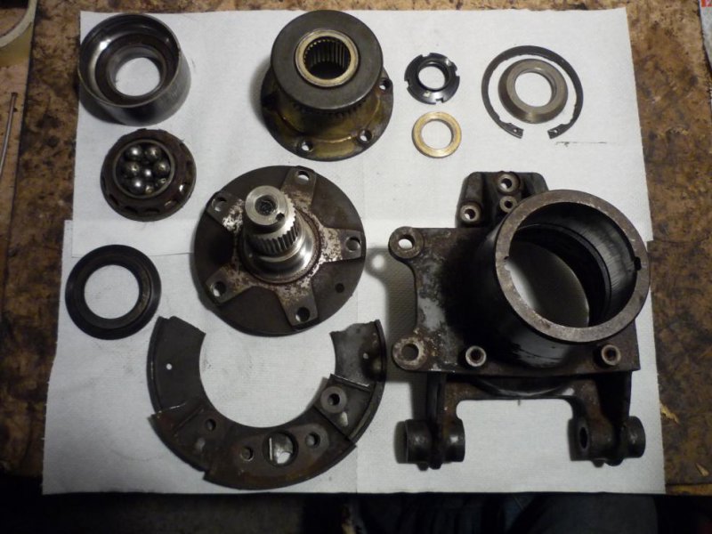
Finally 2-2 bottom ones are out, hubs are separated. The shorter top ones are still holding strong. Heat, hitting, turning, cursing did help. Left side was easier, but one of the screws on the right side came out really badly and wrecked havoc on the hub / arm sleeve too.

P1060394.jpg

P1060396.jpg

Already found a right hand arm, but do you think I can use the hub like this?

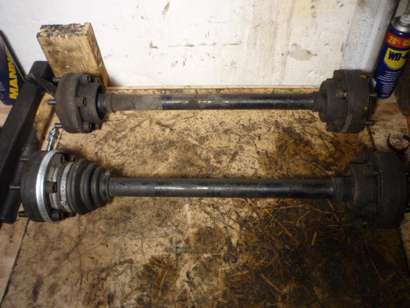
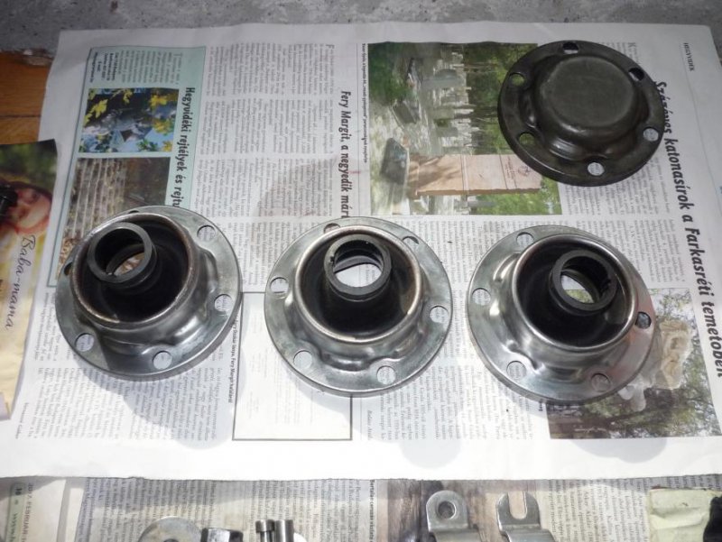
Another question: how to remove the half shafts? Do I have to separate the boots with the metal part? One of them was replaced recently because the boot was torn, as I remember with a BMW part.

P1060398.jpg
 

del mar

Junior Member
Messages
257
The three original ones - no.

The rubber boot is fixed to the metal part, you tap the metal part off the cv joint, and it all comes apart.

I managed to clean up my cv joints, powder coat the shafts and had the rubber boots refinished so the metal parts were gold again.
 

spacecadet

Member
Messages
378
Hi,

sorry for the lack of update, was away for a month, but have finally some progress to report

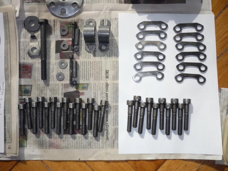
Spent hours and hours cleaning all the bolts and small pieces in rust dissolver and with a wire wheel to prepare for plating. Of course the platers could remove the rust, but I was told, the more shinier before the better it will come out.

P1060447.jpg

P1060451.jpg

More hours spent on removing old Dinitrol (brown), sandblasters don't like these things because the media gets contaminated.

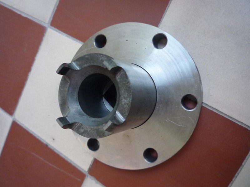
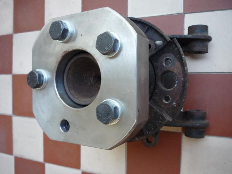
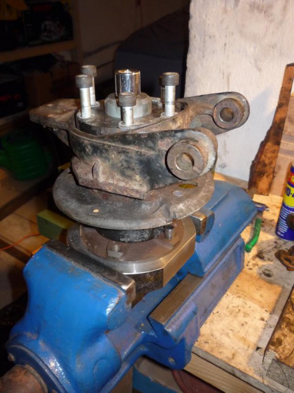
Meanwhile got a custom made tool from a CNC shop for the hubs

It has 3 pieces
- socket for the ring nut
- a ring for the socket so it doesn't tilt, needs 300Nm per the manual
- a counter piece, so the whole thing can be clamped into a vice

P1060456.jpg

P1060457.jpg

P1060454.jpg

I've tried to disassemble one of the spare hubs I sourced recently (because of the scored bores on mine) today, but no luck, even though my longest pipe was 1m long...

P1060464.jpg
 

spacecadet

Member
Messages
378
Drive shaft disassembly

These are also disassembled, here is how I did it

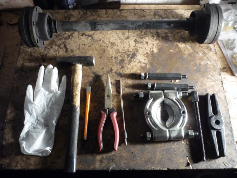
Tools needed:
- chisel / flat-head screwdriver and hammer do remove the metal caps / boots
- seeger ring pliers, only had small screwdrivers
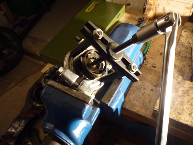
- bearing puller, CV joint were stuck on the shaft
- gloves, paper towels, rags; lots of them

P1060432.jpg

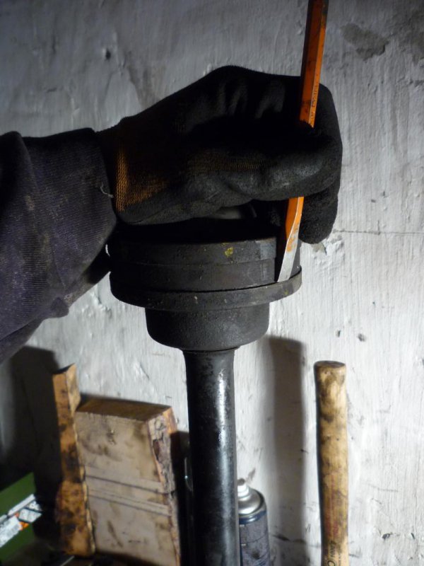
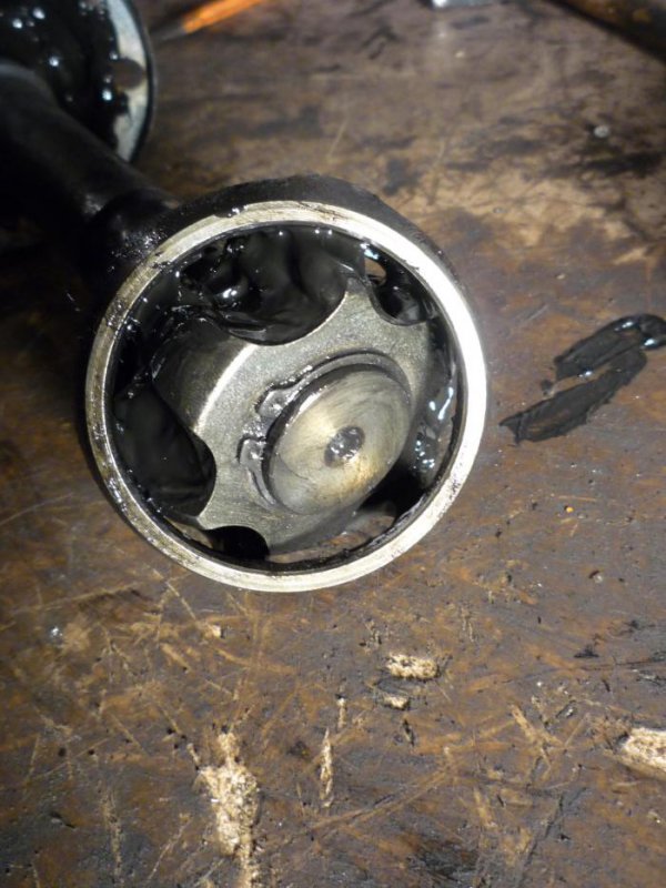
Remove the rubber boots, first remove the clips holding them, then drive down with a chisel

P1060433.jpg

The outer part of CV joint can be removed then after removing some of the balls

P1060440.jpg

Then Remove the seeger ring

P1060441.jpg

And pull down the inner part and the cage

P1060443.jpg

All cleaned up

P1060461.jpg

For the reference:

- Seeger ring: A28 (had one missing)
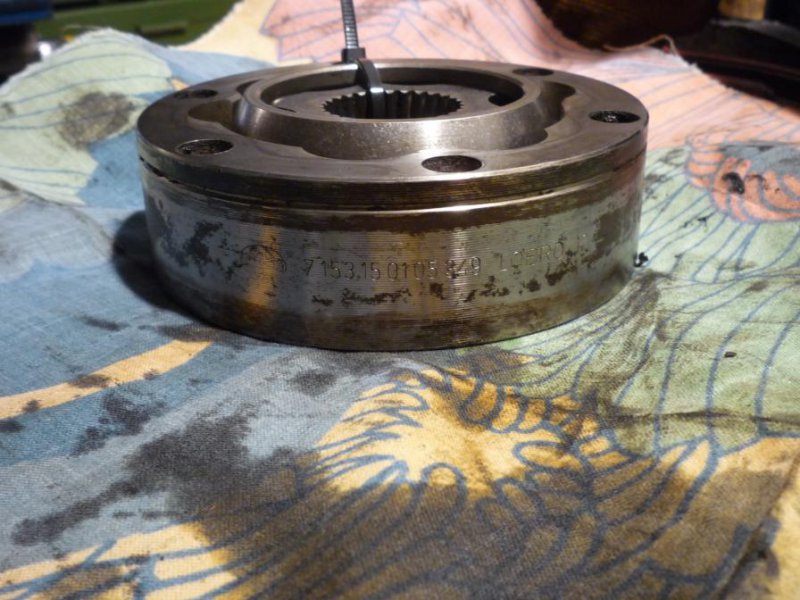
- CV Joint: Lobro 7153150105349, OD: 108mm, L: 32mm, splines no.: 28, bores no.: 6, bore: 10.2mm, PCD: 94mm; probably the same as in a BMW M5 (E34) which is a GKN 302294
- Boot: the closest I've found is a GKN Aero (from GKN Motorsport division), MS6N003, see in http://www.gknservice.com/fileadmin/user_upload/Brochures/English/Motorsport_Catalogue.pdf; will order and verify to replace the mismatched one
 

spacecadet

Member
Messages
378
I would like to get some opinions about how to refinish the parts

Initially I was thinking on e-coat + 2K epoxy primer and paint, but the companies (big*ones) doing e-coating are not dealing with sandblasting, so I have to sync this as much as possible to avoid flash rusting and such. E-coat sounds great because it can go everywhere not possible with other painting methods. Although I've found out that the inside of the subframe is filled with Tectyl done in 2000.

The other option is powder coating which I was afraid of because of the stories about chipping and such. But the other side (as always) praises it. Del how is yours holding up?

For the powder I found a good looking system: Interpon PZ System, which is a 2-3 coat system, powder finish over a zinc filled epoxy powder primer which gives cathodic protection if the top coat damages.

Plascoat also sounds good, but couldn't find a distributor or applicator locally.
 
Messages
397
Really useful putting all this info here spacecadet, thanks. I'm sure (if it hasn't already) this will become a very valuable resource for anyone attempting the same job. Anything that helps keep these classic Maseratis running has to be a good thing!
 

spacecadet

Member
Messages
378
Rear hub diassembly

Thanks, I got so much help from reading the forum, I hope to contribute back something useful too. So here it goes then. I started with a spare hub as an experiment (indeed I broke the plate as seen above)
00.jpg

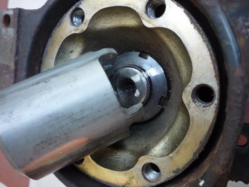
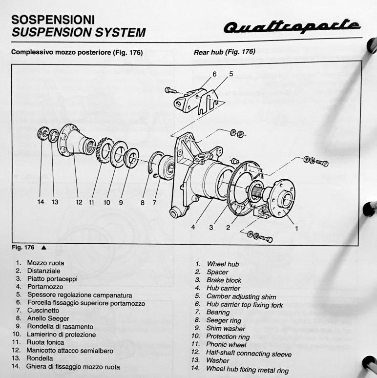
I wanted to weaken the ring nut (14) which I got stuck last time, but it turned out it just needs more torque to open, by the manual it has to be torqued to 30 kgm.
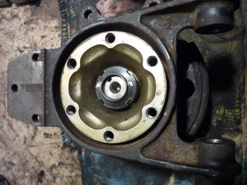
01.jpg

The washer (13) and the sleeve (12) together with the phonic ring (11) and the protection ring (10) will just slide down from the hub shaft.
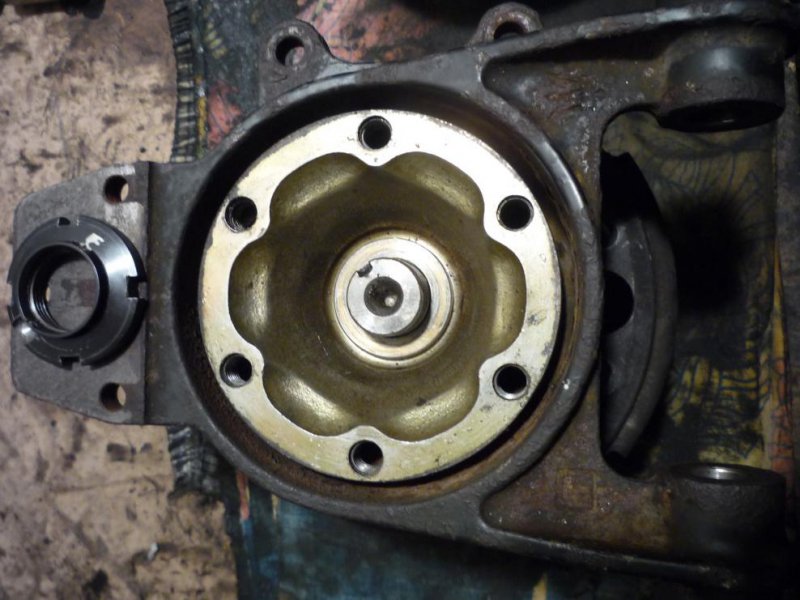
02.jpg

There is a big seeger ring (8) which will probably needs some force to remove because of the corrosion inside.
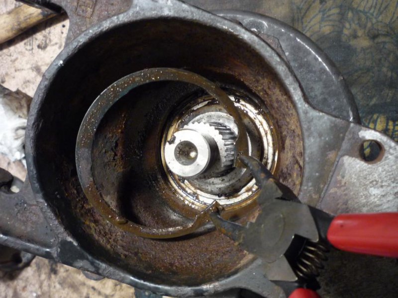
03.jpg

The washer on top of the bearing (9) might simply slide down if the hub is turned upside-down, or will be removed after the hub is pushed out. Which is the second most hardest part. You have to unscrew the brake shoe holding plate (3) from the hub first. The screws will be either corroded, or have some thread locker on them. So definitely apply a lot heat to break up these, especially for the allen head ones, which are quite easy to strip. I even broke one which holds the ABS sensor, welded a nut on it, and the heat lossened it nicely.

To push out the hub (1) support the hub carrier itself (4) and not the brake plate which is from a really rigid and fragile alloy. Also be prepared that the balls of the bearing will fall out, put some clothes below to catch them.
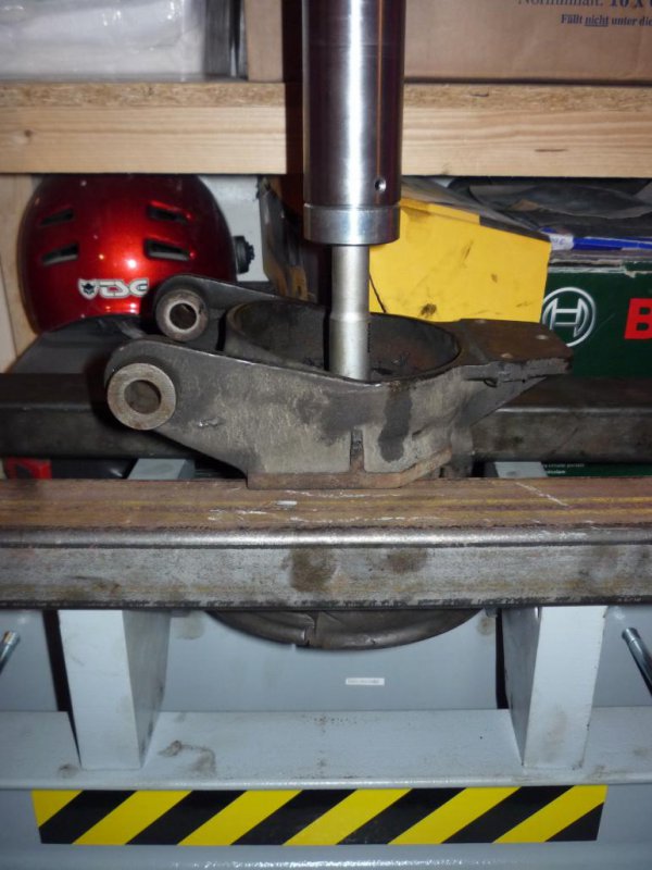
04.jpg

The bearings (7) are double row ball bearings, SKF BAH-0004 A, the inner race of the outer row will stay on the hub shaft.
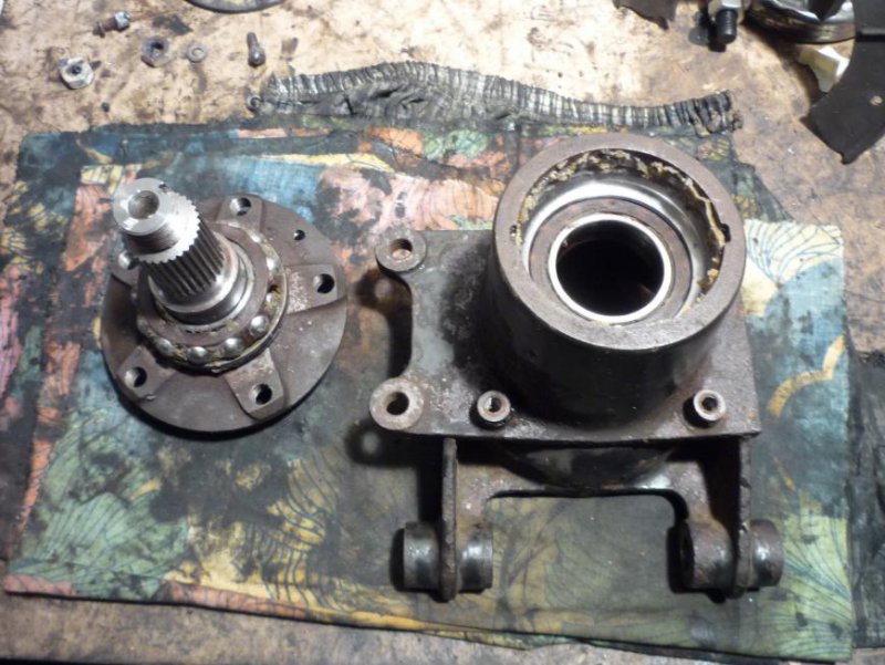
05.jpg

The outermost part of the bearing can be removed before tackling the inner race.
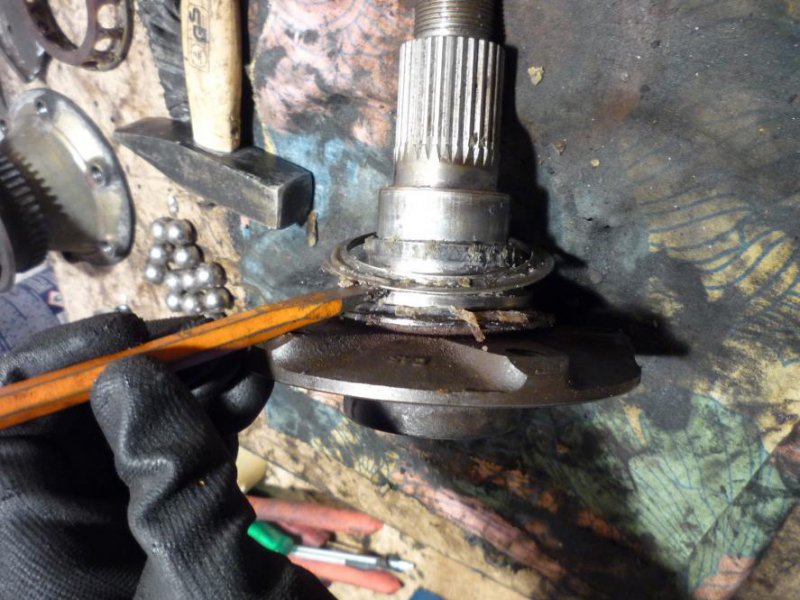
06.jpg

Removing the inner race was the hardest / most frightening part for me. I'm sure there are various methods for this, I choose to cut two groves with an angle grinder and use a bearing separator to pull down the race.
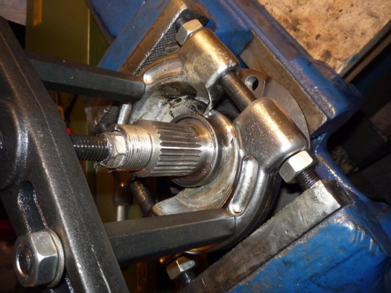
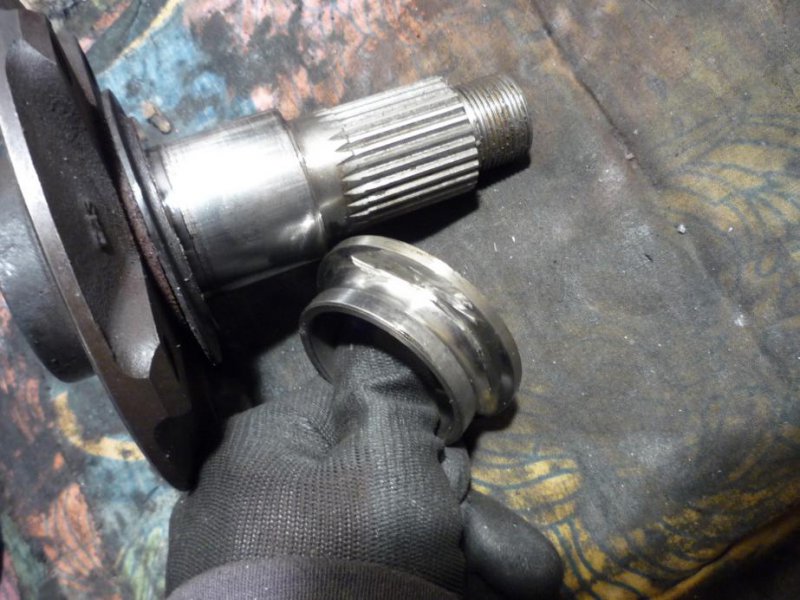
07.jpg

08.jpg

After it's down the spacer (2) will simply slide down.

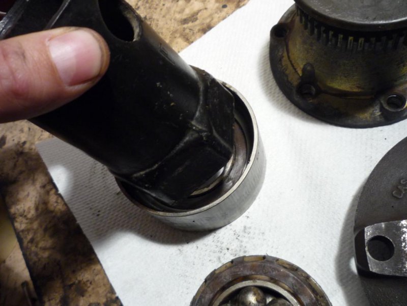
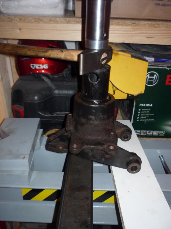
Finally pushing out the outer race is pretty easy with a properly sized tool which sits on the lips of the outer race.
09.jpg

10.jpg

Now the hub carriers are ready to be properly refinished. I'm still waiting for the damaged sleeves of the arm and hub to be repaired. Then will take everything to the painter. I'll probably go with some epoxy primer + 2K topcoat, because of the Tectyl in the subframe is not really compatible with the baking process of the poweder coating.

Couldn't decide though what is the original method, there is no primer below the black layer, but also doesn't look so thick as powder coat.
 

spacecadet

Member
Messages
378
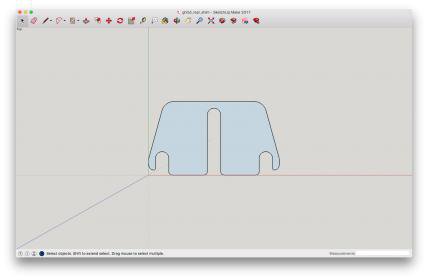
Is anyone interested in shims for setting up the rear wheel camber? Planning to laser cut 1mm and 2mm (Maserati part no. 397050370 and 397050357) from stainless steel and I would happily give away some.

Screen Shot 2017-05-07 at 18.44.16.jpg
 

chad5k1

New Member
Messages
167
I guess each car is different, but we didn't need the shims on standard suspension and we don't need it on aftermarket either - the shims reduce rear camber.
 

spacecadet

Member
Messages
378
There were some in both on L and R side, one or two factory shim and some trash metal sheet shoved in there. Also the requirement might change over time as all the arms I have seen, also talked to a few other owners, have a small bend on the upper pipe, probably caused by hitting the chassis.

Is there an aftermarket solution? Could you give some info about it? Is it a custom one you made or off the shelf?
 

chad5k1

New Member
Messages
167
We are running HYR coilovers, reducing height increases negative camber, but it never gets close to excessive.
 

ZAM400209

Member
Messages
585
the quality of info in this, is unreal!

we could develop a second factory-manual from posts like this...!