4200 Radio & Satnav upgrade

HTAFC4200

Member
Messages
503
It's not been a totally successful day. Had a 50/50 chance hooking up the pioneer unit to the handbrake, tried the first wire, didn't seem to make a difference, tried the 2nd wire, exactly the same. Just ended up re-insulating the first wire and who knows whether the feature will work or not after all of that lol
 

HTAFC4200

Member
Messages
503
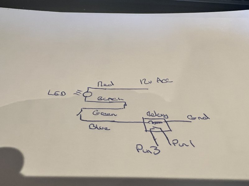
Pin 1 on what? The relay or the switch? But I don't think so. You don't want red, blue and green connected to each other.

I suspect @Zep knows the cable colours to the flasher relay which may be an easier way of doing it.

C
Pin 1 on the oem iso connector which went to the back of the factory display unit.

Bridging pins 1 and 3 makes the hazards work so that's where the switch comes in.
 

CatmanV2

Member
Messages
48,859
So *probably* green to pin one and red/blue to pin 3. Possibly red/blue to 1 and green to 3, but I'm assuming that pin 1 is +12v. Black to ground.

C
 

Zep

Moderator
Messages
9,311
Pin 1 on the oem iso connector which went to the back of the factory display unit.

Bridging pins 1 and 3 makes the hazards work so that's where the switch comes in.

So you need to measure which one has voltage on it and that will be the (in theory) 12v feed. Which goes to the common on your new switch.
 

HTAFC4200

Member
Messages
503
Thanks for the help.

Pin 1 is 12v pin3 is gnd.

When I connected green to pin 1 and blue and black to ground the hazards work, but the switch light fails to illuminate.

Bring the live red into the mix either on pin 1 (it illuminates permanently) or pin 3 not at all.
 

CatmanV2

Member
Messages
48,859
Try putting green on 3 and red+blue on one. I don't think it'll work but it will eliminate it. Red and blue need to be together.

C
 

HTAFC4200

Member
Messages
503
I'll update with my progress, it's just process of elimination at this point lol

Then I've got to find a feed for the reverse line into the pioneer unit and a feed from a lighting circuit to send into pin 6 of the same iso as the hazards.
 

Zep

Moderator
Messages
9,311
Aha, so the load is on the hot side.

New plan is pin 1 to red, black to green, blue to pin 3 or ground at your choice.
 

HTAFC4200

Member
Messages
503
Aha, so the load is on the hot side.

New plan is pin 1 to red, black to green, blue to pin 3 or ground at your choice.
So red to 12v
Black and green together
Blue to gnd

Press the button, red light comes on, no hazards.
 

Zep

Moderator
Messages
9,311
So red to 12v
Black and green together
Blue to gnd

Press the button, red light comes on, no hazards.

Did you try it to pin 3?

If so and it didn’t work it seems the LED is adding too much impedance to trigger the hazards, so it will need a relay. Thinking about it another way, would it not be better to illuminate the switch when the lights are on?
 

HTAFC4200

Member
Messages
503
Pin 3 is the gnd

I'm only working with 2 wires from the car loom, pin 1 and pin 3, 12v and gnd respectively.
 

Zep

Moderator
Messages
9,311
Pin 3 is the gnd

I'm only working with 2 wires from the car loom, pin 1 and pin 3, 12v and gnd respectively.

Ok, so you have two choices without a relay, light on or light off. To have it on when the switch is on, you will need a relay so the BCM sees a clean ground when the switch is made.
 

HTAFC4200

Member
Messages
503
I had the hazards working and the switch light flashing together, but it was intermittent, obviously a loose connection.